GPS Applications in Crop Production
John Nowatzki, Extension Geospatial Specialist
Vern Hofman, Extension Ag Engineer
Lowell Disrud, Assistant Professor
Kraig Nelson, Graduate Student
The Global Positioning System (GPS) provides opportunities for agricultural producers to manage their land and crop production more precisely. Common names for general GPS applications in farming and ranching include precision agriculture, site-specific farming, and prescription farming. GPS applications in farming include guidance of equipment such as sprayers, fertilizer applicators, and tillage implements to reduce excess overlap and skips. They can also be used to precisely locate soil-sampling sites, to map weed, disease, and insect infestations in fields, and to apply variable rate crop inputs and, in conjunction with yield monitors, record crop yields in fields.
How Is GPS Used in Farming?
Equipment Guidance Systems
Lightbar-guided and automated steering systems help maintain precise swath-to-swath widths. Guidance systems identify an imaginary A-B starting line, curve or circle for parallel swathing using GPS positions and a control module. The module takes into account the swath width of the implement and then uses GPS to guide machines along parallel, curved, or circular evenly spaced swaths. Guidance systems include a display module that uses audible tones or lights as directional indicators for the operator. The guidance system allows the operator to monitor the lightbar to maintain the desired distance from the previous swath. Guidance systems require two principle components: a lightbar or screen, which is essentially an electronic display showing a machine’s deviation from the intended position, and a GPS receiver for locating the position (Figure 1). This receiver must be designed for this purpose and it must operate at a higher frequency (position calculations are usually 5 to 10 times per second) than a GPS receiver designed to record positions for a yield monitor. GPS receivers designed for guidance can be used in conjunction with a yield monitor or for other positioning equipment. Automated steering systems integrate GPS guidance capabilities into the vehicle steering system. Automated steering frees the operator from steering the equipment except at corners and at the ends of fields. Guidance systems base prices are approximately $3,000, including the GPS receiver and a readout unit. Systems that steer the vehicle will be higher priced.
Yield Monitoring Systems
Yield monitoring systems typically utilize a mass flow sensor for continuous measuring of the harvested weight of the crop. The sensor is normally located at the top of the clean grain elevator. As the grain is conveyed into the grain tank, it strikes the sensor and the amount of force applied to the sensor represents the recorded yield. While this is happening, the grain is being tested for moisture to adjust the yield value accordingly. At the same time, a sensor is detecting header position to determine whether yield data should be recorded. Header width is normally entered manually into the monitor and a GPS, radar, or a wheel rotation sensor is used to determine travel speed. The data is displayed on a monitor located in the combine cab and stored on a computer card for transfer to an office computer for analysis. Yield monitors require regular calibration to account for varying conditions, crops, and test weights. Yield monitoring systems cost approximately $3,000 to $4,000, not including the cost of the GPS unit.
Field Mapping with GPS and GIS
GPS technology is used to locate and map regions of fields, such as high weed, disease, and pest infestations. Rocks, potholes, power lines, tree rows, broken drain tile, poorly drained regions, and other landmarks can also be recorded for future reference. GPS is used to locate and map soil-sampling locations, allowing growers to develop contour maps showing fertility variations throughout fields. The various datasets are added as map layers in geographic information system (GIS) computer programs. GIS programs are used to analyze and correlate information between GIS layers.
Precision Crop Input Applications
GPS technology is used to vary crop inputs throughout a field based on GIS maps or real-time sensing of crop conditions. Variable rate technology requires a GPS receiver, a computer controller, and a regulated drive mechanism mounted on the applicator. Crop input equipment, such as planters or chemical applicators, can be equipped to vary one or several products simultaneously.
Variable rate technology is used to vary fertilizer, seed, herbicide, fungicide, and insecticide rates and for adjusting irrigation applications. The cost of all of the components necessary for variable rate application of several products is approximately $15,000, not including the cost of the GPS receiver. Technology capable of varying just one product costs approximately $4,000.
How Does the GPS System Work?
The GPS System
Precisely locating positions on Earth is not a new phenomenon. Navigators, sailors, explorers, and surveyors have done this for centuries as they traveled about the world. Most maps and globes display longitude and latitude or some other coordinate projection information. Points on Earth are given unique addresses on maps using specific coordinate systems. Agriculturists commonly use either a geographic system of latitude and longitude measured in degrees or a Universal Transverse Mercator coordinate system that locates positions in meters measured from a specific point. The GPS system uses measured distances to the precisely located GPS satellites to locate positions on Earth. Radio receivers in GPS units monitor radio signals broadcast from the GPS satellites. A GPS position is determined by simultaneously measuring the distance to at least three satellites. The distance to a satellite is measured by the time it takes a radio signal to travel from the satellite to the GPS receiver. Computers in GPS units use information from the radio signals, including broadcast time and unique satellite information, to calculate positions. Information from at least four satellites is needed to calculate elevation. Signal reception from more satellites increases position accuracy. The global positioning system includes a constellation of 24 systematically arranged satellites orbiting Earth in six orbital planes with four satellites in each plane. The satellite orbits are approximately 12,500 miles above Earth. The constellation is arranged to guarantee radio reception from at least four satellites from any location anytime, anywhere on Earth (Figure 3). GPS receivers normally receive signals from eight to nine satellites in location without obstructions such as buildings or trees.
GPS Errors
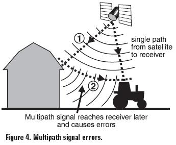
The quality of GPS units and operational errors associated with the GPS system determine the accuracy of GPS-located positions. There are several sources of GPS errors. GPS radio signals can “bounce off” objects such as buildings and trees prior to acquisition by the GPS receiver, resulting in lower accuracy. This is called multipath error. (Figure 4). The satellites use very accurate atomic clocks to generate the timing data received by the GPS receivers. However, even small errors in timing from clocks in the satellites and GPS units cause errors in GPS positions. Signal delay errors can be caused by atmospheric interference such as electrically charged particles in the ionosphere. A layer of water vapor located below the troposphere can also alter the speed of travel of radio signals. Errors from GPS satellites’ orbit and location are also significant. Pressures from solar radiation and gravitational forces of the sun and moon can alter satellite locations. GPS receiver quality also affects GPS accuracy. More costly GPS units generally provide more accurate GPS positions than less expensive units.
What Is Differential Correction?
Types of Correction
Differential global positioning systems (DGPS) reduce GPS errors and provide more accurate and reliable readings. Differential correction uses a radio signal broadcast from known locations on Earth. These Earth-based stations receive radio signals from the GPS satellites and determine the error from their known positions. The error is calculated and transmitted to the GPS receivers (Figure 5). The U.S. government and several commercial companies provide differential correction GPS services. The U.S. Coast Guard provides a free differential correction beacon signal. The Coast Guard signal is an AM radio signal that is broadcast from several locations and travels as a “ground wave” over the Earth’s terrain. Each station has a radial coverage of approximately 300 miles. As the distance increases, the accuracy of the signal decreases. This system was originally designed for use on U.S. navigable waterways (Figure 6) but is being expanded to provide coverage over much of the United States.
Several commercial geostationary satellite differential correction services are available for subscription charges. These systems use known Earth-based stations that receive GPS satellite signals and determine the amount of error. The corrected signal is broadcast to a geostationary satellite, which in turn broadcasts the corrected signal to the subscribed GPS receivers. (Figure 7)
The Wide Area Augmentation System (WAAS) differential correction system uses a network of 25 ground-based reference stations. The U.S. Federal Aviation Administration operates the WAAS differential correction service to provide accurate GPS positions for commercial aircraft. The reference stations relay GPS-determined locations to a master station. The master station calculates a correction factor that is transmitted to geostationary satellites (Figure 8). WAAS-enabled GPS units receive the corrected signal from the WAAS geostationary satellite. The WAAS system uses two geostationary satellites located over the East and West coasts of the United States.
Real-Time Kinematic Differential Correction
A fourth type of differential GPS correction, commonly called real-time kinematic GPS (RTK GPS), provides GPS position accuracy to within 1 centimeter. RTK GPS requires a separate base station located within approximately 5 miles of the mobile GPS units. The RTK base station is a known location equipped with a GPS unit. The base station GPS location is corrected to its known location, and the correction factor is transmitted to the mobile GPS units by FM radio signals. The accuracy of RTK GPS results from the close proximity of the base correction station.
Levels of Accuracy – Receiver Types – Costs
GPS units for precision agriculture applications require sub-meter accuracy, must incorporate differential correction, and are priced from approximately $1,500. Handheld GPS units without differential correction locate positions within about a 30-foot radial area and range in price from less than $100 to many times that amount. Some handheld GPS units are available with differential correction. RTK GPS systems cost several times as much as common sub-meter accuracy GPS unit used in agriculture.
References
Ess, D., & Morgan, M., (1997). The Precision-Farming Guide for Agriculturists. (1st ed.). Moline, IL.
Stombaugh, T., Shearer, S., Fulton, J., (2002). GPS Simplified. 2002 University of Kentucky Ext. Rept. PA-5.
Yeung, A. K. W., & Lo, C. P., (2002). Concepts and Techniques of Geographic Information Systems. Upper Saddle River, NJ.


